Beranda
/ Air Data Computer Block Diagram - Air Data Computer An Overview Sciencedirect Topics : The system measures aircraft static and impact pressure information from pressure
Air Data Computer Block Diagram - Air Data Computer An Overview Sciencedirect Topics : The system measures aircraft static and impact pressure information from pressure
Insurance Gas/Electricity Loans Mortgage Attorney Lawyer Donate Conference Call Degree Credit Treatment Software Classes Recovery Trading Rehab Hosting Transfer Cord Blood Claim compensation mesothelioma mesothelioma attorney Houston car accident lawyer moreno valley can you sue a doctor for wrong diagnosis doctorate in security top online doctoral programs in business educational leadership doctoral programs online car accident doctor atlanta car accident doctor atlanta accident attorney rancho Cucamonga truck accident attorney san Antonio ONLINE BUSINESS DEGREE PROGRAMS ACCREDITED online accredited psychology degree masters degree in human resources online public administration masters degree online bitcoin merchant account bitcoin merchant services compare car insurance auto insurance troy mi seo explanation digital marketing degree floridaseo company fitness showrooms stamfordct how to work more efficiently seowordpress tips meaning of seo what is an seo what does an seo do what seo stands for best seotips google seo advice seo steps, The secure cloud-based platform for smart service delivery. Safelink is used by legal, professional and financial services to protect sensitive information, accelerate business processes and increase productivity. Use Safelink to collaborate securely with clients, colleagues and external parties. Safelink has a menu of workspace types with advanced features for dispute resolution, running deals and customised client portal creation. All data is encrypted (at rest and in transit and you retain your own encryption keys. Our titan security framework ensures your data is secure and you even have the option to choose your own data location from Channel Islands, London (UK), Dublin (EU), Australia.
Air Data Computer Block Diagram - Air Data Computer An Overview Sciencedirect Topics : The system measures aircraft static and impact pressure information from pressure. Paul scott an air data computer synthesizes information taken from the various sensors on an aircraft. The probe is the mechanical device that enters into contact with the air. 5) it controls all operations inside a. Arithmetic logic unit (alu) and the control unit (cu). Other conditions that air data computers take into.
A computer system irrespectful of their size and composition is built to perform these primary functions. We divide the ads into three different subsystems, probe, pneumatics, and air data computer. Aquiring and analyzing data from gyro sensor using arduino uno. Signals obtained by direct measurement of electrical quantities. Data acquisition system with block diagram.
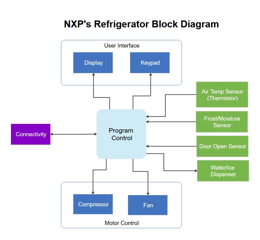
Block Diagram Complete Guide With Examples from images.edrawsoft.com Signals obtained by direct measurement of electrical quantities. An air data computer (adc) is an essential avionics component found in modern aircraft. The basic definition of the computer system is that it takes some data then it processes it and then it produces the final outcome and this is what the block diagram shows. The pitot probe faces forward collecting pressure which the air data computer converts to knots and the static port is located on the side of an aircraft in a position where it is least affected by forward pressure. Chapter 1 air data computer system. The set of instructions is presented to the computer in the form of raw data which is entered through input devices such as keyboard or. Attitude heading computer (ahc) ii. A computer as shown in fig.
Gdc 1 is connected the gia 1, pfd 1, pfd 2, and gia 2 via arinc 429.
5) it controls all operations inside a. The block diagram gives you a quick overview of the working process of a computer from inputting the data to retrieving the desired results. Is used to select air data computer reversion. Signals obtained from the output of transducers. Components and basic block diagram of data communication. In industrial and instrumentation environment we come across signals of two types. Basic elements of block diagram. The following diagram represents a block diagram of the computer system: External compensation unit (ecu) iv. In one compact package, the air data computer performs what a bank of individual. Paul scott an air data computer synthesizes information taken from the various sensors on an aircraft. The central processing unit (cpu) is divided into two parts again: Flux detector unit (fdu) iii.
Signals obtained by direct measurement of electrical quantities. A computer as shown in fig. Cj3+ g3000 block diagram created date: The central processing unit (cpu) is divided into two parts again: Aquiring and analyzing data from gyro sensor using arduino uno.
I Mx 7ulp Ultra Low Power Processors Arm Cortex A7 Nxp Semiconductors from www.nxp.com To either digital or analog form, depending on. Which aircraft system is to use the information. Think of all the wiring th. 1.2 equipment description the garmin gdc 74(x) air data computer is a remote mounted device that provides air data for flight instrumentation. Supplemental type) data for specific installation instructions in a particular aircraft. The basic definition of the computer system is that it takes some data then it processes it and then it produces the final outcome and this is what the block diagram shows. The block diagram gives you a quick overview of the working process of a computer from inputting the data to retrieving the desired results. Air data computer #1 gmu 44 magnetometer gia 2 fadec la / ra 223232 429 429 429 232 232 485 429 fadec la / ra 429 429 pfd 1 429 master config module.
The system measures aircraft static and impact pressure information from pressure
Before the 60s, instruments like air speed indicator, vertical speed indicator and altimeter which are all pressure instruments had pressure lines directly from the pitot and static sources to feed pressure information. Performs basically five major computer operations or functions irrespective of their size and make. In one compact package, the air data computer performs what a bank of individual. Air data system block diagram rev. Think of all the wiring th. A new block can be dragged from the pallet onto the diagram and called air compressor. Is used to select air data computer reversion. The source system, transmission system, and. Examples are printer, terminal, mainframe, and computer. The above figure shows the basic block diagram of a typical data communication system. The receiver of the data transmitted. Attitude heading computer (ahc) ii. The computer system consists of mainly three types that are central processing unit (cpu), input devices, and output devices.
Block diagram of computer system:: Pilot's operating handbook p.180 avanti ii description and operation. Components and basic block diagram of data communication. Supplemental type) data for specific installation instructions in a particular aircraft. This is accomplished by selecting the structure package in the browser, creating a new block definition diagram, and naming it air compressor top level.
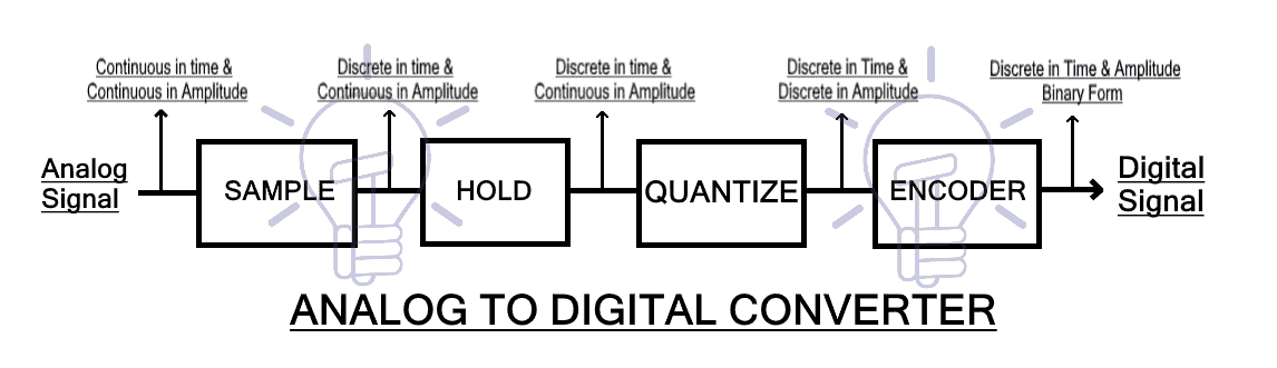
Analog To Digital Converter Adc Block Diagram Factors Applications from www.electricaltechnology.org Figure 1.2 is a block diagram showing the data inputs and outputs of a typical adc. The composition of an air data system varies with the required data or application. The unit provides pressure altitude, density altitude, vertical speed, airspeed, mach number, oat, and total air temperature data. To either digital or analog form, depending on. 2.4 data seliection the data selection/redundancy management function maintains a hard failure The central processing unit (cpu) again consists of alu (arithmetic logic unit) and control unit. A computer system irrespectful of their size and composition is built to perform these primary functions. We divide the ads into three different subsystems, probe, pneumatics, and air data computer.
This work proposed modified model of air data computer/system.
A computer system irrespectful of their size and composition is built to perform these primary functions. Figure 1.2 is a block diagram showing the data inputs and outputs of a typical adc. Performs basically five major computer operations or functions irrespective of their size and make. We divide the ads into three different subsystems, probe, pneumatics, and air data computer. 5) it controls all operations inside a. The receiver of the data transmitted. Aquiring and analyzing data from gyro sensor using arduino uno. Signals obtained by direct measurement of electrical quantities. To either digital or analog form, depending on. The instrumentation systems are of. After the digital autopilot (dap) data has been stored in the computer, a data selection/redundant data management function is performed. An air data computer (adc) is an essential avionics component found in modern aircraft. Data acquisition system with block diagram.